Parts Included
Prior to preforming this procedure you will need to have the ASCARDREAD1 assembly and a small bag of hardware.
SEALTIGHT01 cable gland
ITPRCBL printer cable
Tools Needed
Prior to performing this procedure, you will need to have the following tools:
- Flat screwdriver
- Phillips screwdriver
- 1/8” drill bit
- ¾ “ drill bit
- Adjustable wrench
Installation
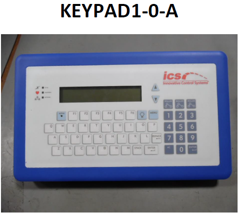
- Look at the left side of the KEYPAD1-0-A. There should be a cable gland for the power and data cables. There may also be a knock-out plug below it. If there is a knock-out plug, open the back of the KEYPAD1-0-A unit by removing the 12 screws along the back outer edge. Remove the knock-out plug with a flat screwdriver. If there is not a knock-out plug, continue next with the instructions for drilling the hole for the new printer cable and cable gland.
- Cut out the drilling template below (along the solid black line). You will use this to drill the hole for the cable gland and ITPRCBL cable.
- Hold the template from above along the left side of the KEYPAD1-0-A. Mark the location of the hole to be drilled with a center punch and drill a 1/8” pilot hole. Then drill the hole to final size of ¾” diameter.
- Disassemble the SEALTIGHT01 cable gland as shown below. The rubber O-ring, if it has one, will not be used.
- Insert the threaded end of the cable gland into the KEYPAD-0-A so the threads are inside the enclosure. Apply a small amount of silicone caulk to the threads. Attach the cable gland nut and gently tighten with an adjustable wrench.
- Feed the end of the ITPRCBL printer cable through the cable gland. Find the green header marked “GND – RXD – TXD – 5V”. Connect the solid blue wire to GND, the white wire with blue stripe to RXD, and the solid yellow wire to TXD. If there is a white wire with orange stripe, cut it off at the end of the outer insulation, it will not be used.
- Tighten the cable gland on the outside of the enclosure around the ITPRCBL printer cable to keep the unit water-tight. Re-attach the back of the enclosure to the front, using the 12 screws removed earlier.
Please contact ICS Technical Support if any assistance is needed:
800-246-3469
INSTR0057
Comments
0 comments
Article is closed for comments.